Front Panel
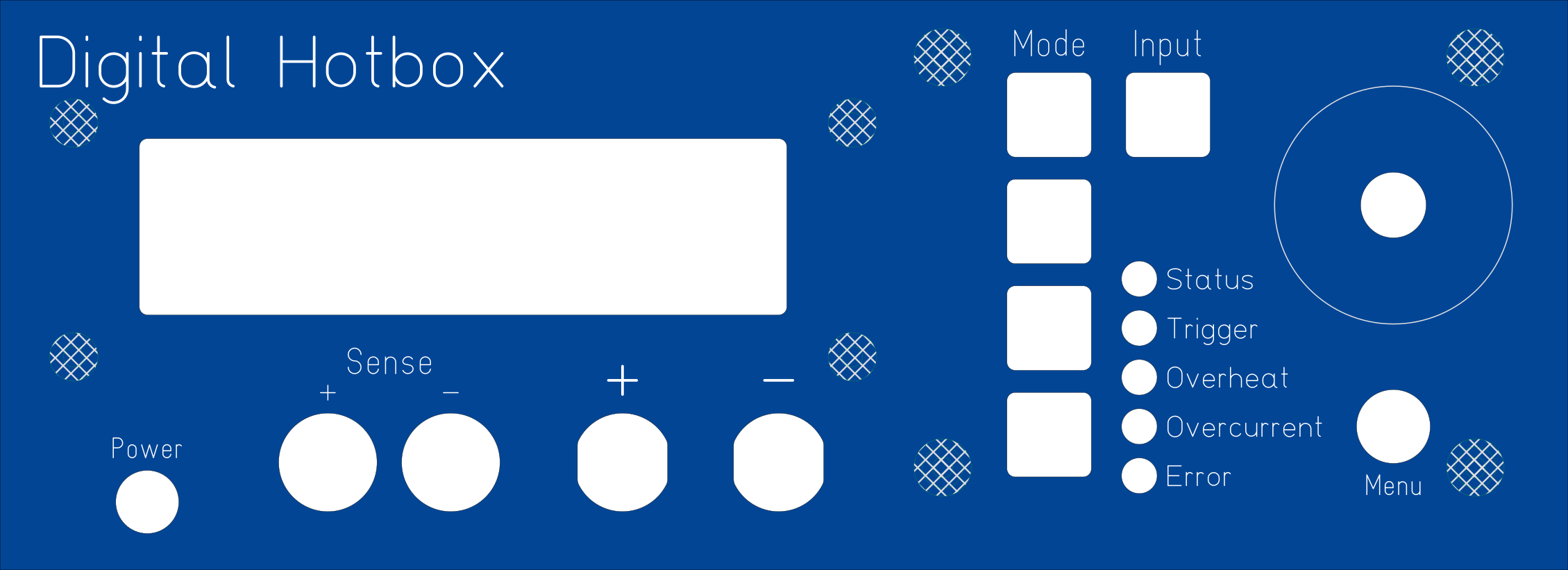
The front panel features a few buttons, indicators, and a rotary encoder.
Overview
Note that the actual front panel board only covers the right third of the actual front panel: the area with the push buttons, indicators, and rotary encoder. It's mounted to the case via four 8mm standoffs with M2.5 thread, and should be screwed in with washers to distribute the force of button pushes more evenly across the board, rather than stressing the screw holes.
Connectors
There are two primary connections to the rest of the world on the front panel: the external voltage sense input, and the supply input.
External voltage sense may or may not be used for measurement, depending on software control.
Supply input is made through a pair of binding posts (Cal Test CT4231) supporting up to 36A per post. The positive and negative terminals follow the standard red/black convention, and are internally connected to the driver board via thick wiring. The binding posts should use some sort of screw mount for the wire, which itself should have crimped ferrules or other terminals on the end to attach conveniently to the wire.
External sense voltage is delivered through a pair of banana jacks (Cal Test CT2240.) These do not need to carry much current (if any) and are on a yellow and black connector (for positive and negative, respectively) there. These jacks are solder mount, which should be soldered to a (possibly shielded) twisted pair wire, which in turn connects to the driver board's external voltage sense input.
Buttons
The bulk of the buttons on the front panel consists of illuminated tactile switches (Omron B3W-9 type), which are further subdivided into the mode selectors (column of four switches, each with a single yellow LED) and the input on/off button (one switch, with dual red/green LEDs.)
Additionally, the button inside the rotary encoder (triggered when the knob is depressed) is available as a switch for selecting items in menu. It works in conjunction with the circular menu button (C&K D6R type) to browse menus.
On the front panel, all buttons are connected to a XRA1203 I²C IO expander. It features an interrupt output, which is connected to the controller board so buttons needn't be polled in software.
Lastly, there is a power button in the lower left corner; this switch actually exists on the controller board, rather than the front panel. It's an illuminated, right angle tactile switch (CTS 228A type) with the appropriate power icon (the little circle with the dash on it) printed on its cap. The board is set up to support bi-color illuminated switches so that there can be a standby/active type lighting situation.
Indicators
Indicators are LEDs, which are brought out to the front panel via light pipes. These indicators consist of one RGB LED (status,) one amber LED (trigger,) and three red LEDs (overheat, overcurrent, error.) Each LED can be individually controlled, and its brightness (current) adjusted.
All LEDs are connected to a PCA9955B constant current LED driver.
Display
Any SPI display is compatible with the front panel, though it is specifically designed for the ER-OLEDM032-1Y module (or any other compatible modules with other colors; do note that the display may need to be modified for 4 wire SPI operation, by soldering some resistors and jumpers) and its pinout.
Regardless of the type of display, it should not consume more than roughly 350mA of current. The main board has a 500mA polyfuse for the display.
The display mounts on 6mm long M2.5 studs, with nylon stand-offs to get the correct distance between the front panel and the display surface. Then, a washer and nut are attached to the end, to fasten the display securely.
Miscellaneous
On the front panel board, there is also an I2C EEPROM (AT24CS32 type) that contains the front panel’s exact configuration, including the switches available, mapping of switch inputs and LED outputs, and LED drive characteristics such as maximum current.
Revisions
Currently, there’s just one revision of front panel, pictured above. It works, but it needs some minor rework:

No Comments