CPU Board
The thing that runs the show
Peripheral Allocation
- CAN0: Expansion
- PA22 (TX), PA23 (RX)
- PA22 (TX), PA23 (RX)
- SERCOM0: I2C, front panel/rear IO (through mux)
- IOSET1
- PA8 (SDA, PAD0), PA9 (SCL, PAD1)
- SERCOM2: I²C, analog board
- PA12 (SDA, PAD0), PA13 (SCL, PAD1)
- SERCOM3: SPI, analog board
- IOSET1
- PA16 (SCK, PAD1), PA17 (MOSI, PAD0), PA18 (MISO, PAD2)
- Chip select: PA19 (/EN)
- Chip index: PB16, PB17
- SERCOM4: SPI, front panel display
- IOSET1
- DIPO = 0x0
- DOPO = 0x2
- PB12 (MISO, PAD0), PB13 (SCK, PAD1), PB14 (/CS, PAD2), PB15 (MOSI, PAD3)
- SERCOM5: SPI, NOR flash (bonus data)
- IOSET6
- DIPO = 0x3
- DOPO = 0x0
- PB2 (MOSI, PAD0), PB3 (SCK, PAD1), PB0 (/CS, PAD2), PB1 (MISO, PAD3)
- IOSET6
- TC3: Fan PWM
- PA14: WO[0]
- TC5: Beeper
- PB10: WO[0]
- EIC: External interrupt controller
- XOSC1: 12MHz oscillator
- XIN (PB22), XOUT (PB23)
- Debug
- SWCLK (PA30), SWDIO (PA31), SWO (PB30)
If desired, the driver communication interface can use CAN0 instead. It uses the same IO pins as the I²C bus, and requires a CAN transceiver on the board.
DMA Channel Allocations
DMAC should operate with dynamic, round-robin priority arbitration within a DMA priority level. Priority levels listed are from 0 (highest) to 3 (lowest.)
- Ch0: NOR flash SPI Tx empty (SERCOM5)
- Priority: 2
- Operate in SPI 32 bit data mode
- Burst transfers
- Priority: 2
- Ch1: NOR flash SPI Rx complete (SERCOM5)
- Priority: 2
- Operate in SPI 32 bit data mode
- Burst transfers
- Ch2: Display SPI Tx empty (SERCOM4)
- Priority: 1
- Operate in SPI 32 bit data mode
- Burst transfers
- Priority: 1
Clocking
Clock Inputs
All clocks on the system are derived from one of the following clock inputs (oscillators and internal generators:)
Crystals
- XOSC1: External 12MHz oscillator
- Provides primary system clock reference
- XOSC32K: External 32.768kHz oscillator
- Runs in standby for RTC
FLLs
- DFLL48M: 48MHz
- Used for USB reference clk
- Uses external 32kHz osc for reference
PLLs
- DPLL0: 120MHz
- CPU core clock
Clock Sources
The above clock inputs are then synthesized into multiple clock sources, each used by a different set of peripherals:
- GCLK0: 120MHz
- Sourced from DPLL0 / 1
- General high speed clock
- GCLK1: 48MHz
- Sourced from DFLL48M
- Intended for USB use
- GCLK3: 32.768kHz
- Sourced from XOSC32K
- SERCOM slow clock
- GCLK4: 12MHz
- Sourced from XOSC1
- General low speed clock
- GCLK5: 32.768kHz
- Sourced from ultra low power 32kHz osc
Clock Consumers
- CPU core: GCLK0
- Clock division factor: /1
- Low power clock: /4
- Backup domain: /8
- High-speed: /1
Hardware Errata
This page lists some issues with CPU board hardware, as they are discovered, and some workarounds.
Rev 1
- /I2C_IRQ's external IRQ line conflicts with ENCODER_A
- Move /I2C_IRQ from PA7 to PA10
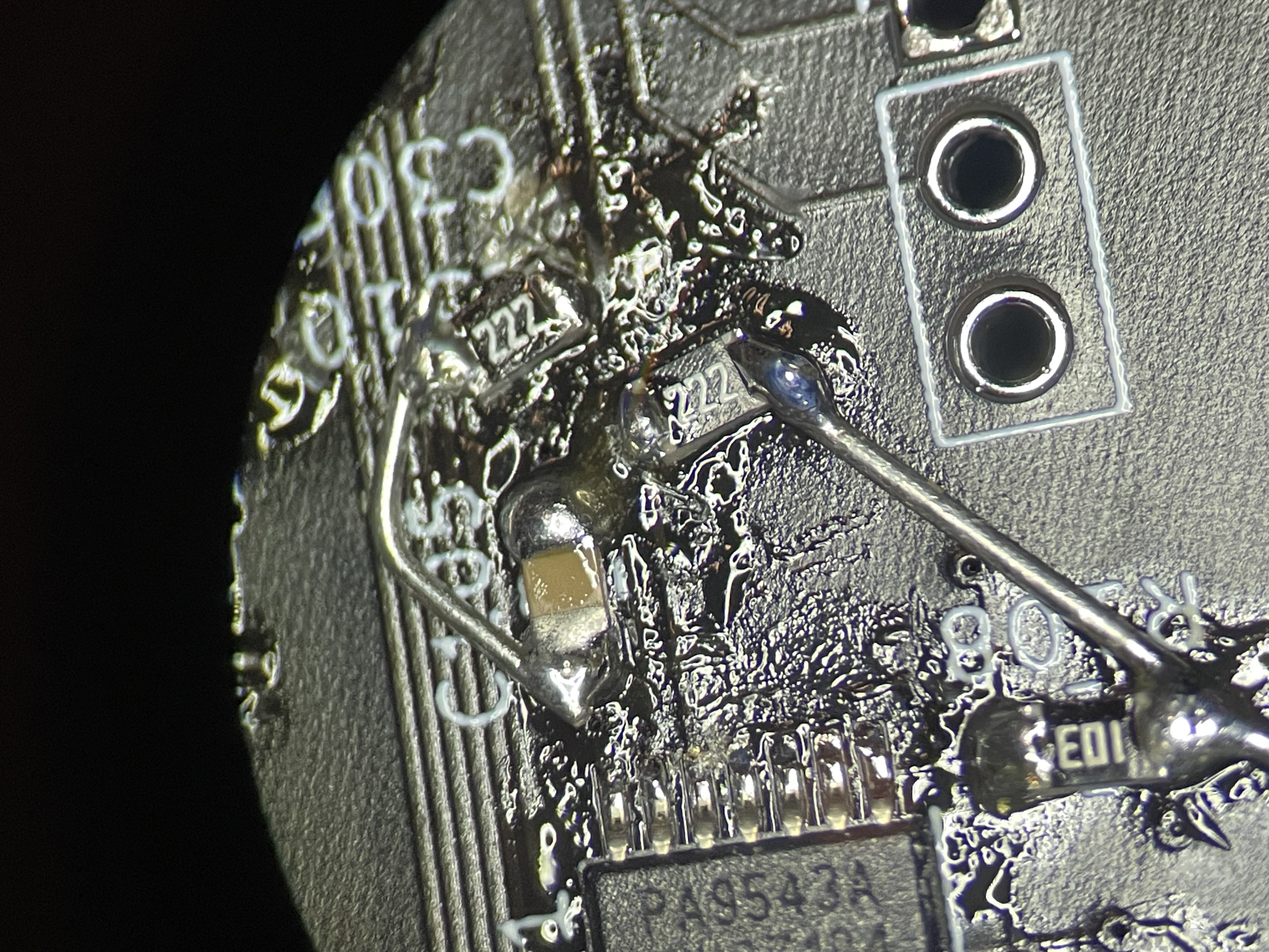
- Rework required: solder line from pin 11 (/IRQ) of U101 to middle of J302 (TXD)
- Status LED (D302) footprint is wrong
- The common (+) and red pins are swapped
- Footprint for MMBT3904 transistors (Q101, Q301) are slightly too small
- The two pads side is slightly too much spacing between pads
- They are still solderable, it just looks ugly
- NOR Flash (U303) is actually 4Mbit
- This is the part I actually had lol
- Power LED driver doesn't work
- The weird trick with the two resistors doesn't seem to work… like, at all
- We'll have to revisit how this is controlled (external logic? sacrificing another pin?)
- Footprint notes
- Copper size on the pads could be increased
- For mechanical retention of the switch, nudge the outer (switch) pads in by a small amount
- Switched front/rear I²C bus (from mux to MCU) is missing pull ups
- Need to insert these between the mux (U101) and microcontroller
- Rework required: Bodge in a pair of 2k2 resistors to +3V3